HX-SPI01-WIFI
-
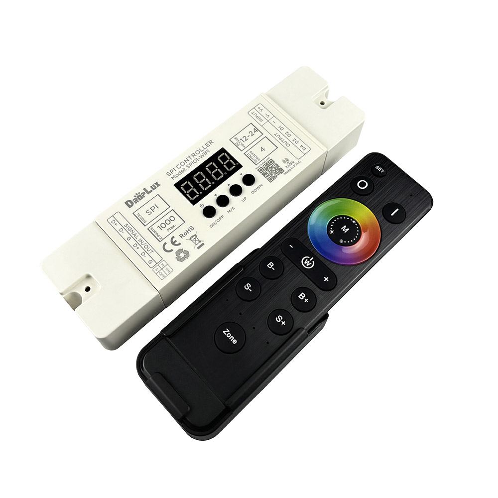
Product Introduction:
HX-SPI01-RFBK controller is suitable for controlling LED lamps driven by a variety of different types of chips. It is widely used in buildings, municipal lighting, stage scenery, entertainment venue decoration, etc.; it can realize horse racing, running water, trailing, color painting, scanning, raindrops Various running change effects; convenient wiring, simple to use; with memory storage function; with digital tube display, which can be controlled by the built-in buttons or with a RF remote con
Product Details
Features
1. This product is a low-voltage SPI controller, the standard product supply voltage is 12-24V;
2. Four groups of SPI signal output ports (three-wire digital led strip), which can control up to 2048 pixels;
3. With digital tube and control buttons, it can also be used with RF remote control for mode selection, speed and IC point adjustment;
4. With power-off memory storage function;
5. Contains 136 effect modes, including horse racing, running water, trailing, color brushing, scanning, raindrops and other effects. The 135th mode is the 8-134th automatic cycle mode, and the 136th is the custom combination mode;
6. The controllers can realize multiple synchronous changes through shielded wire connection;
7. The remote control has 4 areas of overall control or independent control functions
8. This product is guaranteed for three years, excluding man-made damage, improper operation, overload short circuit or force majeure factors.
Technical Parameters:
Controller:
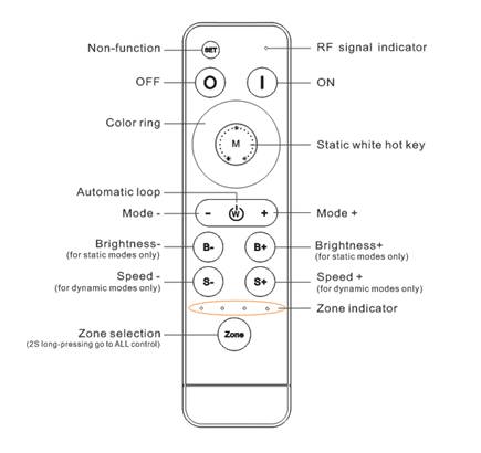
Remote control:
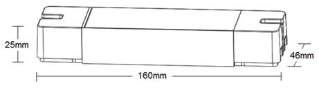
Dimension
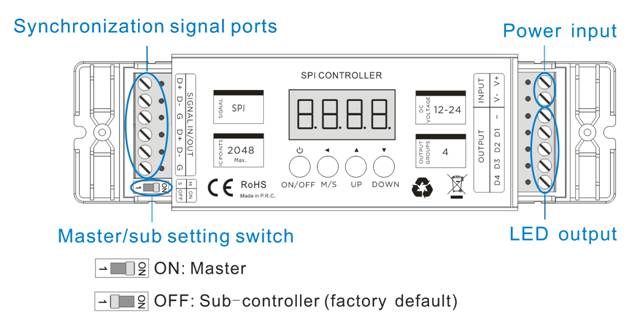
Connection ports
Instructions for use
Step 1: In the off state, long-press the "M/S" and "Up" buttons at the same time for 2 seconds to enter Custom combination mode settings, the digital tube will light up and display "-**-", "-**-" represents the currently edited scene number. Please use the "UP" / "DOWN" keys to select the scene number to be edited. For example, we will set a custom combination mode with 5 modes.
Step 2: Setting the mode for -01-. Press "M/S" after Step 1 "-01-", the digital tube will display "H***". Please use the "UP" / "DOWN" keys to select the needed mode from 1-134th for "-01-". If the digital tube displays “H000”, mean there is no effect was set to current scene.
Step 3: Setting the speed for -01-. Press "M/S" after Step 2, the digital tube will display "S-**". Please use the "UP" / "DOWN" keys to select the needed speed from 01-99 for "-01-" mode. The status of loading led strips will be changed accordingly.
Press "M/S" after Step 3, the digital tube will display back to "-01-". Please press "UP" / "DOWN" keys to select the next edited scene number, and repeat the operation like step2 and step 3 to finished the all other 5 scenes from 2nd to 6th. And press the "ON/OFF" key to save and exit in the end.
Important notes: When there are less than 20 scenes set, the scene should start from -01- the first number (because the 136th mode runs from scene “01”), and the scenes without effect need to be set to “H000”. Like example that we set 5 scenes to combinate the 136th mode, enter the edit menu and edit the respective modes and speeds of scenes "-01-" to "-05-" (can be not in order during the editing operation). After editing, please check the mode of scene "-06-" should be "H000", if not, please correct it by the "UP"/"DOWN" keys.
After all the controllers are connected according to the wiring diagram (please make sure the position of the DIP switch of the master and the sub-controller is correct), just turn on the master, and the sub-controllers will change according to the speed and mode of the master. The green signal light on the sub-controller will flash in normal working statues.
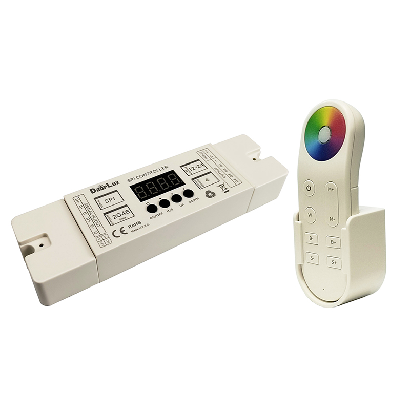
Remote control: RFBK-RGB-2.4G
Mode table
Connection diagram
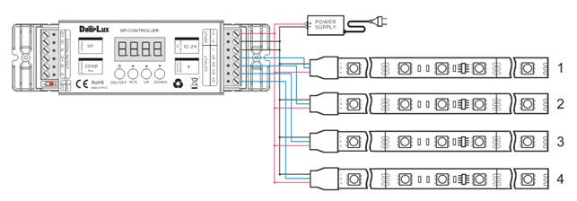
Stand-alone Circuit1:
Synchronization Circuit 2: take the 3-wire digital led strip as an example
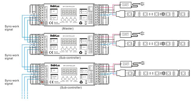
Note: The first one will be the master, please set the DIP switch to ON position; others from the second one will be the sub-control, please keep the DIP switch in the factory default setting -OFF.
About RF code.
The biggest advantage of this system is that it can not only solve the cabling problem in engineering wirelessly, but also realize a wired-like operation experience. In order to facilitate the early testing and debugging of the project, the factory status of the receiver is normally unpaired and each remote controller has a unique code value. The user should perform the matching work of the remote controller and the receiver during the installation of the project to avoid the mutual influence of the radio frequency remote control technology during the later use.
Please pay attention to the following 3 points before operation:
1) All equipment in the complete system after installation should have a unified and unique code value, so as to achieve the security and stability of the system.
2) The receiver can only store one code value and cannot be overwritten. Before learning the new code value, it is necessary to clear the original code of the receiver; the remote controller can only save one code value but can be overwritten and can also restore the factory settings. In order to facilitate the later maintenance, the three components that may be involved in the system (including receivers, handheld remote controllers, and panel remote controllers) can realize mutual learning of code values.
3) Since the receiver performs code value learning in the power-on state, batch-operation is available ( power-one the all receivers which will be in same zone, and operate the matching/clearing the RF code all of them at the same time). And in order to avoid confusion in the area, it is recommended that each area has an independent power switch so that the power of other areas can be easily cut off when the code is being operated.
(1)Code pairing operation: means that the receiver will only be controlled by the value code remote controller.
(2)Code clearing operation: means that the original code value of the receiver will be cleared and returned to the factory state. Then it can be controlled by any compatible remote controller and can learn to a new code.
(3)Code learning operation between remote controls: Used to unify system code values or copy a new remote controls.
Since each remote controller has its own unique code at the time of delivery, when there are multiple remote controllers in one system, one of them (for example, remote controller A) must be selected as the system code value, and the code value of the rest remote controllers (for example, remote controller B) should be copied to the same one.
(4) Copying code from receiver to remote control.
A new remote control can also copy code from any one of the receivers in the whole system, after the successful operation, the new remote control can replace the original remote (if it is lost).
* For security of the system, the distance from remote control to the one receiver should be less than 2 meters in this operation.
* Only one time operation is requested for the whole system, no need different operation for different zones.
(5)The remote controller restores the factory setting: it means that the remote controller will be restored to the factory's unique code value.
Malfunctions analysis & troubleshooting
Product information for placing order
1. This product is a low-voltage SPI controller, the standard product supply voltage is 12-24V;
2. Four groups of SPI signal output ports (three-wire digital led strip), which can control up to 2048 pixels;
3. With digital tube and control buttons, it can also be used with RF remote control for mode selection, speed and IC point adjustment;
4. With power-off memory storage function;
5. Contains 136 effect modes, including horse racing, running water, trailing, color brushing, scanning, raindrops and other effects. The 135th mode is the 8-134th automatic cycle mode, and the 136th is the custom combination mode;
6. The controllers can realize multiple synchronous changes through shielded wire connection;
7. The remote control has 4 areas of overall control or independent control functions
8. This product is guaranteed for three years, excluding man-made damage, improper operation, overload short circuit or force majeure factors.
Technical Parameters:
Controller:
| Working temperature | -20-60℃ | Working voltage | DC12-24V |
| Static consumption | <1W | RF frequency | 2.4GHz |
| Gray level | 256 | Speed level | 99 |
| N. weight | 100g | G. weight | 130g |
| Dimension | L160*W46*H25 mm | Packing size | L170*W50*H29 mm |
| Output signal | 4 groups SPI | Max. control points | 2048 |
| RF distance | ≤20m | Modes | 136 |
| Memory function | Yes | Sync-work function | Yes |
| Compatible ICs | UCS1903、WS2811、TM1804、SM16703、17822、ICP943 | ||
| Working temperature | -20℃~60℃ | Supply voltage | DC3V(AAA*2) |
| Standby current | <18uA | Working current | <25mA |
| Standby power | 54uW | Working power | 75mW |
| Net weight | 95g | RF frequency | 2.4GHz |
| External dimension | L150*W40*H20 mm | RF distance | ≤20m |
Dimension
Connection ports
Instructions for use
- Determine the controller is the master or the sub-controller, and set the DIP switch at the right position, master-ON, sub-controller- OFF;
- Connecting the load led strip at first, then connect the power input wires; and make sure that there is no short circuit between the connecting wires before powering on;
- The functions of the 4 buttons on the controller are as follows:
| Button | Function description |
| ON/OFF | Turn on/off |
| M/S |
Switch Mode/speed/brightness adjustment functions Mode adjustment: digital tube display H*** (*** is 000-136, 000 is displayed when controlled by the touch ring on the remote control) Speed adjustment: the digital tube displays S-** (*** is 01-99), the speed adjustment function is only valid for dynamic mode Brightness adjustment: the digital tube displays d*** (*** is 001-100), the brightness adjustment function is only valid for static mode |
| UP | Mode+/Speed+/Brightness+, adjust the object according to the setting result of M/S. |
| DOWN | Mode-/Speed-/Brightness-, adjust the object according to the setting result of M/S. |
- control IC number setting
- Custom combination mode settings
Step 1: In the off state, long-press the "M/S" and "Up" buttons at the same time for 2 seconds to enter Custom combination mode settings, the digital tube will light up and display "-**-", "-**-" represents the currently edited scene number. Please use the "UP" / "DOWN" keys to select the scene number to be edited. For example, we will set a custom combination mode with 5 modes.
Step 2: Setting the mode for -01-. Press "M/S" after Step 1 "-01-", the digital tube will display "H***". Please use the "UP" / "DOWN" keys to select the needed mode from 1-134th for "-01-". If the digital tube displays “H000”, mean there is no effect was set to current scene.
Step 3: Setting the speed for -01-. Press "M/S" after Step 2, the digital tube will display "S-**". Please use the "UP" / "DOWN" keys to select the needed speed from 01-99 for "-01-" mode. The status of loading led strips will be changed accordingly.
Press "M/S" after Step 3, the digital tube will display back to "-01-". Please press "UP" / "DOWN" keys to select the next edited scene number, and repeat the operation like step2 and step 3 to finished the all other 5 scenes from 2nd to 6th. And press the "ON/OFF" key to save and exit in the end.
Important notes: When there are less than 20 scenes set, the scene should start from -01- the first number (because the 136th mode runs from scene “01”), and the scenes without effect need to be set to “H000”. Like example that we set 5 scenes to combinate the 136th mode, enter the edit menu and edit the respective modes and speeds of scenes "-01-" to "-05-" (can be not in order during the editing operation). After editing, please check the mode of scene "-06-" should be "H000", if not, please correct it by the "UP"/"DOWN" keys.
- Synchronization function
After all the controllers are connected according to the wiring diagram (please make sure the position of the DIP switch of the master and the sub-controller is correct), just turn on the master, and the sub-controllers will change according to the speed and mode of the master. The green signal light on the sub-controller will flash in normal working statues.
Remote control: RFBK-RGB-2.4G
| Button | Function description |
 |
Non-function |
 |
ON |
 |
OFF |
| Color ring | Static color options, 64 colors in total, digital tube will display “H000”,brightness is adjustable by B+/B-. |
 |
Static white color hotkey, digital tube will display “H007” |
 |
Automatic loop hotkey, digital tube will display “H135” |
 |
Mode down (136 modes in total). Long-press can get fast adjusting. |
 |
Mode up (136 modes in total). Long-press can get fast adjusting. |
 |
Brightness – for static colors by 100 levels. Long-press can get fast adjusting. |
 |
Brightness + for static colors by 100 levels. Long-press can get fast adjusting. |
 |
Speed down for dynamic mode (100 levels). Long-press can get fast adjusting. |
 |
Speed up for dynamic mode (100 levels). Long-press can get fast adjusting. |
 |
Zone selection, 2 seconds long-press get “all-control”. |
| No. | Mode description | No. | Mode description |
|---|---|---|---|
| 1 | Static Red | 2 | Static Green |
| 3 | Static Blue | 4 | Static Yellow |
| 5 | Static Purple | 6 | Static Cyan |
| 7 | Static White | 8 | 3 color jumping |
| 9 | 7 color jumping | 10 | 7 color flashing |
| 11 | 7 color fading | 12 | Red horse race-right |
| 13 | Blue horse race-right | 14 | Purple horse race-right |
| 15 | Orange horse race-right | 16 | White horse race-right |
| 17 | Cyan horse race-right | 18 | Cyan horse race-left |
| 19 | 7 color horse race-right | 20 | 7 color horse race 2 direction |
| 21 | White 1-pixel horse race-right I | 22 | Red 1-pixel horse race-right I |
| 23 | Green 1-pixel horse race-right I | 24 | Blue 1-pixel horse race-right I |
| 25 | White 1-pixel horse race-right II | 26 | Red 1-pixel horse race-right II |
| 27 | Green 1-pixel horse race-right II | 28 | Blue 1-pixel horse race-right II |
| 29 | White 3-pixel horse race-right | 30 | Red 3-pixel horse race-right |
| 31 | Green 3-pixel horse race-right | 32 | Blue 3-pixel horse race-right |
| 33 | White 5-pixel horse race-right | 34 | Red 5-pixel horse race-right |
| 35 | Green 5pixel horse race-right | 36 | Blue 5-pixel horse race-right |
| 37 | Red and white chasing(right) | 38 | Red, white, blue chasing(right) |
| 39 | Orange and purple chasing(right) | 40 | Orange and blank chasing(right) |
| 41 | Green and white chasing(right) | 42 | Blue and white chasing(right) |
| 43 | Red and yellow chasing(right) | 44 | Orange and blue chasing(right) |
| 45 | Red and blue chasing(right) | 46 | Blue, purple, yellow chasing(right) |
| 47 | Red and green chasing(right) | 48 | Blue and green chasing(right) |
| 49 | Pink and purple chasing(right) | 50 | Yellow and green chasing(right) |
| 51 | Red, yellow, green chasing(right) | 52 | Yellow chasing(right) |
| 53 | Cyan and white chasing(right) | 54 | Cyan and purple chasing(right) |
| 55 | Blue, purple, yellow floating | 56 | Red, green, white floating |
| 57 | Orange, yellow, red floating | 58 | Red, pink floating |
| 59 | Red, white floating | 60 | Blue, white floating |
| 61 | Green, white floating | 62 | All color floating |
| 63 | White random twinkle strobe | 64 | Red running water I |
| 65 | Green running water I | 66 | Blue running water I |
| 67 | Yellow running water I | 68 | Purple running water I |
| 69 | Cyan running water I | 70 | White running water I |
| 71 | Orange running water I | 72 | Cyan trailing right I |
| 73 | Cyan trailing right II | 74 | Cyan trailing left |
| 75 | Running back and forth with Cyan | 76 | Running back and forth with Purple |
| 77 | Red running water II | 78 | Green running water II |
| 79 | Blue running water II | 80 | Yellow running water II |
| 81 | Purple running water II | 82 | Cyan running water II |
| 83 | White running water II | 84 | 7-color running water II |
| 85 | Cyan trails water to the right I | 86 | Cyan trails water to the right II |
| 87 | 7-color trails water to the right | 88 | Red single trailing right |
| 89 | Purple single trailing right I | 90 | Blue single trailing right |
| 91 | Cyan single trailing right | 92 | White single trailing right |
| 93 | Green single trailing right | 94 | Yellow single trailing right |
| 95 | 7-color jumping single trailing right | 96 | 7-color queue single trailing right |
| 97 | 7-color in turn single trailing right | 98 | Cyan double trailing left |
| 99 | Red double trailing right | 100 | Purple double trailing right |
| 101 | Blue double trailing right | 102 | Cyan double trailing right |
| 103 | White double trailing right | 104 | Green double trailing right |
| 105 | Yellow double trailing right | 106 | 7-color jumping double trailing right |
| 107 | 7-color queue double trailing right | 108 | 7-color in turn double trailing right |
| 109 | 7-color running water III | 110 | Blue double trailing on Red |
| 111 | Red double trailing on Blue | 112 | Green double trailing on Blue |
| 113 | Blue double trailing on Green | 114 | Red double trailing on Green |
| 115 | Green double trailing on Red | 116 | White double trailing on Blue |
| 117 | Double trailing on 7-color | 118 | 7-color opening brushing |
| 119 | 7-color closing brushing | 120 | 7-color open-closing |
| 121 | 7-color closing | 122 | Red closing |
| 123 | Green closing | 124 | Blue closing |
| 125 | Yellow closing | 126 | Purple closing |
| 127 | Cyan closing | 128 | White closing |
| 129 | 7-color stacking right | 130 | 7-color stacking |
| 131 | 6-color opening stacking | 132 | 6- color closing stacking |
| 133 | 7-color moving | 134 | 7-color brushing |
| 135 | Auto loop playback (8-134) | 136 | User-defined combination mode |
Stand-alone Circuit1:
Synchronization Circuit 2: take the 3-wire digital led strip as an example
Note: The first one will be the master, please set the DIP switch to ON position; others from the second one will be the sub-control, please keep the DIP switch in the factory default setting -OFF.
About RF code.
The biggest advantage of this system is that it can not only solve the cabling problem in engineering wirelessly, but also realize a wired-like operation experience. In order to facilitate the early testing and debugging of the project, the factory status of the receiver is normally unpaired and each remote controller has a unique code value. The user should perform the matching work of the remote controller and the receiver during the installation of the project to avoid the mutual influence of the radio frequency remote control technology during the later use.
Please pay attention to the following 3 points before operation:
1) All equipment in the complete system after installation should have a unified and unique code value, so as to achieve the security and stability of the system.
2) The receiver can only store one code value and cannot be overwritten. Before learning the new code value, it is necessary to clear the original code of the receiver; the remote controller can only save one code value but can be overwritten and can also restore the factory settings. In order to facilitate the later maintenance, the three components that may be involved in the system (including receivers, handheld remote controllers, and panel remote controllers) can realize mutual learning of code values.
3) Since the receiver performs code value learning in the power-on state, batch-operation is available ( power-one the all receivers which will be in same zone, and operate the matching/clearing the RF code all of them at the same time). And in order to avoid confusion in the area, it is recommended that each area has an independent power switch so that the power of other areas can be easily cut off when the code is being operated.
(1)Code pairing operation: means that the receiver will only be controlled by the value code remote controller.
| Step | Operation | Instructions |
| 1 | Connecting the load to the receiver and power on it. |
1.It is necessary to clear the code first, if the receiver was coded before. 2.Batch operation can be performed within the remote control range. |
| 2 | Select area | Select the area with the "Zone" key and the corresponding indicator lights up |
| 3 | Press and hold “ON” on the remote control for 5 seconds, the indicator of the remote control will flash quickly, means it enters the pairing code transmission status. | Will automatically exit code transmission status after 60 seconds, or pressing any key to exit. |
| 4 | See the load light flashes 3 times and return to the initial state | Pairing coding is finished successfully |
| Step | Operation | Instructions |
| 1 | Connecting the load to the receiver and power on it. |
1. The clearing operation should be finished within 1 minute after the receiver is powered on. If exceeds the time, can be powered on again. 2. Batch operation can be performed within the remote control range. |
| 2 | Press and hold the remote control “Off” for 5 seconds. The indicator of the remote control flashes quickly, means it enters the clearing code transmission status. There is no need to select the corresponding area when clearing code. |
1. Will automatically exit code transmission status after 60 seconds or pressing any key to exit. 2. If the original remote controller is lost, the new remote controller can be used for clearing operations. |
| 3 | See the load light flashes 3 times and return to the initial state | Clearing coding is finished successfully |
Since each remote controller has its own unique code at the time of delivery, when there are multiple remote controllers in one system, one of them (for example, remote controller A) must be selected as the system code value, and the code value of the rest remote controllers (for example, remote controller B) should be copied to the same one.
| Step | Operation | Instructions |
| 1 | A remote control:Press and hold “ON” on the remote control for 5 seconds, the indicator of the remote control will flash quickly, means it enters the pairing code transmission status. | Will automatically exit code transmission status after 60 seconds, or pressing any key to exit. |
| 2 | B remote control: long press "mode key" for 5 seconds, the remote indicator light changes from 100% light to off, means entering the code value receiving state | Will automatically exit the code value receiving state after 30 seconds, or exit after learning the code value successfully. |
| 3 | see the B remote control indicator light flash 3 times | Code copying is finished and exit code value receiving status. |
A new remote control can also copy code from any one of the receivers in the whole system, after the successful operation, the new remote control can replace the original remote (if it is lost).
| Step | Operation | Instructions |
| 1 | Cut off the power of receiver. | Which one will be controlled by remote. |
| 2 | Long-press "mode key" for 5 seconds, the remote indicator light changes from 100% light to off, means entering the code value receiving state. | Will automatically exit the code value receiving state after 30 seconds, or exit after learning the code value successfully. |
| 3 | Power on the receiver, will see remote control indicator light flash 3 times. | Code copying is finished and exit code value receiving status. |
* Only one time operation is requested for the whole system, no need different operation for different zones.
(5)The remote controller restores the factory setting: it means that the remote controller will be restored to the factory's unique code value.
| Step | Operation | Instructions |
| 1 | Long press "mode " for 20 seconds | The remote indicator light dim down continuously until the 20th second and then back to 100% light. Means this step is finished. |
| 2 | Press the "OFF" to confirm, the remote indicator light flashes 3 times | Restore factory settings successfully. |
| Malfunctions | Causes | Troubleshooting |
| No light |
1. No power. 2. Wrong connection or insecure. 3. Wrong setting. |
1. Check the power. 2. Check the connection. 3. Check the setting. |
| Out of sync when using the sync function |
1. Wrong DIP switch setting. 2. Wrong connection or insecure. |
1. Check the DIP switch setting. 2. Check the connection. |
| No response from the remote |
1. The battery has no power. 2. Beyond controllable distance. 3. The controller did not match the remote. |
1. Replace battery. 2. Reduce remote distance. 3. Re-match the remote. |
| Product name | Item number |
| LED digital Controller with remote control | HX-SPI01-RFBK |

 Jane-Hoion